Software EcmWin
The EcmWin software is written in the C++ programming language in an object-oriented form. The user interface is Windows™ standard and therefore offers optimum ease of use. The use of standardized dialogs makes it easy for users to find their way around the software. An online help function provides explanations for all dialogs. A keyword-based help function in the footer provides up-to-date information
EcmWin is essentially divided into three method groups:
- Standard measurement methods for simple operation
- File-based methods for more complex functions
- Sequence methods for almost any measurement sequence
The standard measurement methods are simple functions for performing resting potential measurement, hold test, linear and cyclic sweep, and pulse measurement with few settings.
The desired measurement method is first selected in the main measurement window. In the case of a hold test, scan, pulse, or file, the resting potential can be measured before and/or after.
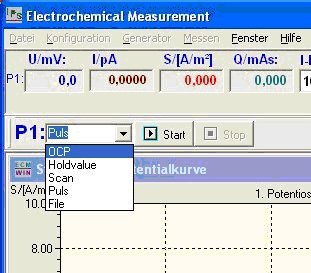
Then the corresponding settings windows for scan or pulse are opened.
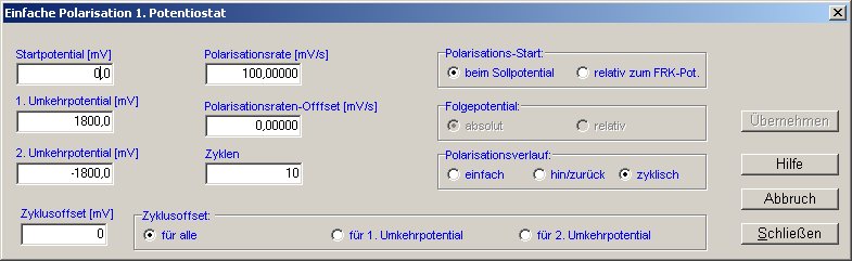
For scanning, the starting potential, first and second reversal potentials, polarization rate, and number of cycles are entered. The result looks as follows:
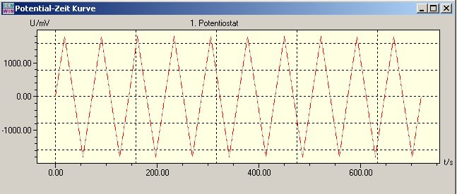
Optionally, each cycle can also be assigned an offset, or the polarization rate can also be changed by a defined value with each offset.
The same applies to pulse generation. If a homogeneous pulse is required, it is defined as follows:
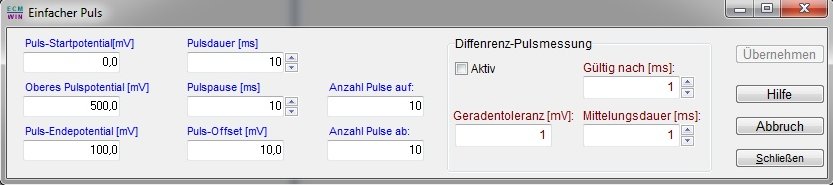
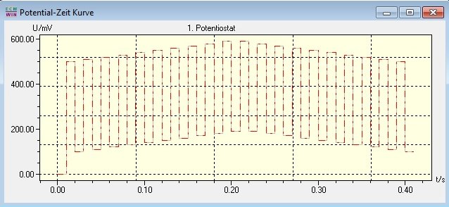
In addition to the lower and upper pulse potential, it is also possible to run the pulses up and down via a ramp, as shown in the following image.
If more complex polarization curves are required, it is possible to create a control file that contains the following function, for example:
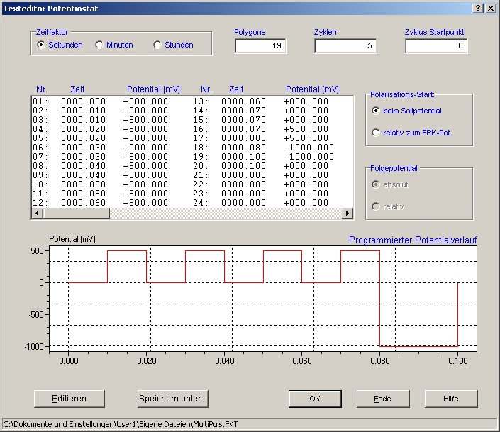
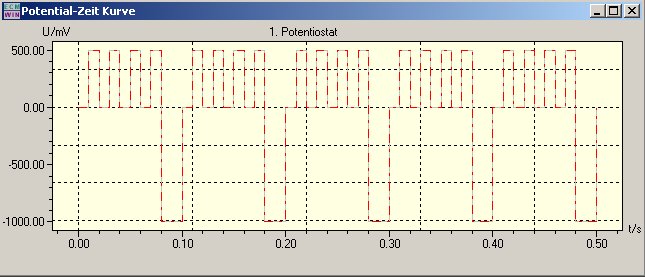
The function generated in this way can be run once or cyclically. With 5 cycles, as in this example, this results in the following diagram:
Such functions can be generated and processed separately for both potentiostatic and galvanostatic modes using hold values, jumps, and ramps.
For even more complex functions, such as cycling batteries or fuel cells, EcmWin also includes sequence measurement. The following image shows the corresponding dialog for generating such a function:
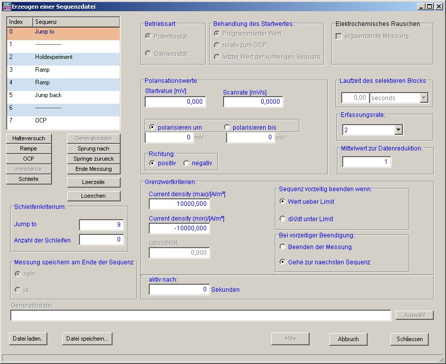
This sequence function allows you to perform resting potential measurement, hold test, ramp, loop, jump, electrochemical noise, and impedance in potentiostat and galvanostat modes. Each sequence has its own limit value data set and sample rate. After any sequence, the current measurement file can be closed and a new one opened. This means that parts of the measurement data are available even before the end of the measurement. Jumps are linked to a loop counter so that certain sections can be executed several times.
Some of our devices have switchable inputs for external polarization signals. These can also be switched on or off by sequence. There are no limits to flexibility here.
The following image shows a typical measurement window. In addition to the standard current density-potential curve, all variables can also be displayed over time. Furthermore, all measured values are displayed digitally with their respective units. If the current range of the potentiostat is switched, the dimension of the current is updated immediately. A reference electrode correction value can be entered to normalize the potential, and the sample size can be entered to calculate the current density.
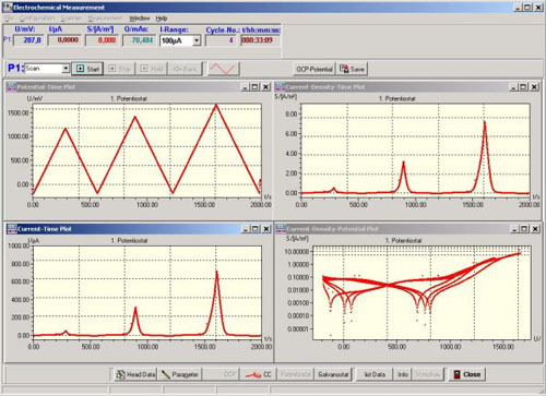
In addition:
Each measurement can also be canceled manually by the user.
The Start, Stop, Hold, and Back buttons are used for interactive control of the measurement sequence.
The buttons header data and parameter dare used to enter descriptive texts and measurement parameters, respectively.
The Save button is used to save the measurement, End to close all measurement windows.
The potentiostat/galvanostat and free corrosion potential/I-cell operating modes can also be switched manually.
Impedance measurement (optional)
Impedance measurement is an additional module of our EcmWin software. It only works with the corresponding potentiostat and external or built-in additional hardware. As in other function modules, we also distinguish between automatic and manual operation here.
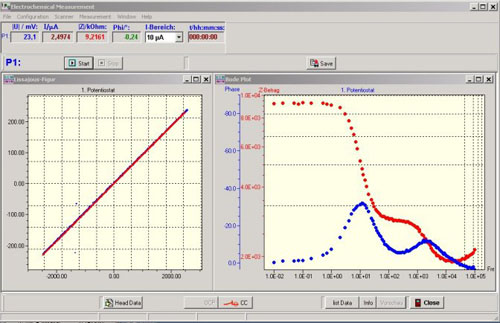
In manual mode, the desired frequency can be entered. The sine wave signals for current and voltage, the impedance value, and the phase shift are displayed on the screen. If the measured values are valid, a switch is enabled to accept the measurement point. When the user presses this switch, the current measuring point is saved with the frequency, phase, U, I, Z amount, real and imaginary parts of the impedance. In addition, the measuring point is entered into the locus curve graph.
Advantages of this measuring principle:
In automatic mode, a file with preset frequencies is loaded and processed. The program sets the frequencies, measures potential and current, displays the values, and calculates the desired quantities. Then the next frequency value is set.
- All measurement processes are displayed transparently
- If certain measurement points (frequencies) need to be examined more closely, they can be reset and analyzed again in manual mode