Hydrogen permeation
This document is a sort of guide to the different system variants for research and investigation of hydrogen permeation that we are aware of. For each option, there is an indication of any existing systems that may be integrated in such an acquisition and that may change the budget. Depending on the circumstances, it must be considered if it is economically feasible to integrate already existing systems with eventually high effort. Under certain circumstances, restrictions on the possibilities of use must be taken into account. This paper addresses the topics of component testing in a hydrogen atmosphere and hydrogen permeation. The field of electrolysis and fuel cells is not covered here. Our statements focus on engineering considerations and the presentation of systems from the user perspective.
In hydrogen diffusion or permeation, a distinction must be made between atomic and molecular hydrogen. Electrochemical methods typically produce atomic hydrogen, which is more prone to diffusion than molecular. In the case of pressure methods, this is usually molecular hydrogen, although it would still be necessary to investigate which combinations are feasible.
Promoting forces for diffusion are pressure, mechanical deformation and temperature. A combination of these factors has the greatest effect, depending on the application.
Electrochemical methods with atomic hydrogen
Based on the presumption that electrochemical systems such as potentiostats/galvanostats with measuring cells exist in many laboratories, and that tensile testing machines are also frequently present, this consideration begins with hydrogen permeation with the use of a Devanathan Cell. This is a mechanism to which most electroplating coaters today must pay attention. During the various steps of such a plating process, atomic hydrogen is produced, either by chemical reaction or by application of a current, which has a tendency to diffuse into a metal, for example, at grain boundaries. Here, the coater must prove that the amount of hydrogen that diffuses into the material does not result in a significant weakening of the material strength. Corresponding tests can be carried out with a Devanathan cell.
The material to be tested is placed between the two half-cells of this cell. On the so-called charging side, hydrogen is generated either by chemicals or by electrochemistry, while on the measuring side the permeated hydrogen is measured.
In order to perform this experiment successfully, certain constraints may be necessary. Due to the scientific background, these should be read in published dissertations or publications.
Thus, to perform this experiment, a devanthan cell is required as the central element, as well as at least one potentiostat/galvanostat and an appropriate chemical. If two potentiostats are available, the experiment can be performed in an even more focused manner. In addition, the devanthan cell can be tempered and, if a tensile device is available, the sample can also be exposed to a tensile load during the experiment.
Another option is to use a potentiostat with a standard measuring cell. Here, a round or flat sample can be connected as a working electrode and polarized with cathodic potential in the hydrogen production region. If necessary, the cell is additionally tempered. After a certain exposure time, the specimen is removed from the cell, placed in a tensile machine and stretched until fracture occurs. Then the fracture pattern can be examined optically and compared with an unstressed specimen. This is also a method with certain boundary conditions, but one that does not require any additional investment if the above-mentioned equipment is available. The next variant is the use of a so-called TubeCell. A round specimen is installed in this type of cell and mounted in a tensile machine. Now the sample can be mechanically loaded in the machine. Either a chemical or an electrochemical method can be used as an additional load. The fracture pattern of the sample is again the criteria for analysis here. This cell is currently built for room temperature only. However, this could be equipped with a double jacket or with a heating coil in the cell vessel, so that temperature can be controlled here.
Pressure variants with molecular hydrogen
The simplest method here is a small autoclave in which the specimen to be tested is placed and then filled with pressurized hydrogen. An improvement would be a small tensile device (constant load) or a four-point flexure specimen, which is placed in the autoclave with the specimen clamped. In this case, however, the autoclave must be larger. If the autoclave is additionally temperature-controlled, an additional impact factor is added. In terms of price, such a system is in the lower segment of pressure tests.
The next variant is the so-called hollow specimen technique. The first publication on this subject dates back to 1984 on the occasion of the 60th birthday of Prof. Dr.-Ing. Hans Schlachter.
Here a tensile specimen is drilled hollow. Hydrogen with pressure (e.g. 1000bar) is brought into the borehole by an appropriate device. The sample can be mechanically loaded with different methods (SSRT, Cyclic Fatigue). In addition, it can be heated. If the sample fractures, the hydrogen contained in it (and in the feeding piping system) escapes into a vacuum vessel enclosing the tensile device. Due to the small amount of hydrogen and the way the test is carried out, there is no need to define an ATEX zone here, so the safety engineering requirements are moderate. The investments for such a plant are with the tensile testing machine between the before mentioned (with the small autoclaves as well as the static tensile test) and the now following.
From the current perspective, the most sophisticated stage of such a testing system is a plant consisting of a tensile testing machine (preferably servo-hydraulic), an autoclave (20l and more) with a built-in load frame, an enclosure with ventilation (for collecting the escaping hydrogen), a gas management system and a safety-related PLC.
With such a system, specimens can be tested in an ambient pressurized hydrogen atmosphere with slow tension/compression tests or with fatigue tests basically in situ. A thermostat provides the appropriate temperature (-40°C to 200°C). The safety equipment required for such a facility makes it expensive and also costly to operate.
Systems for testing H2 embrittlement
The following figure illustrates the described methods in a context that shows their increasing possibilities and investment volume. The particular methods are summarized once again in the following.
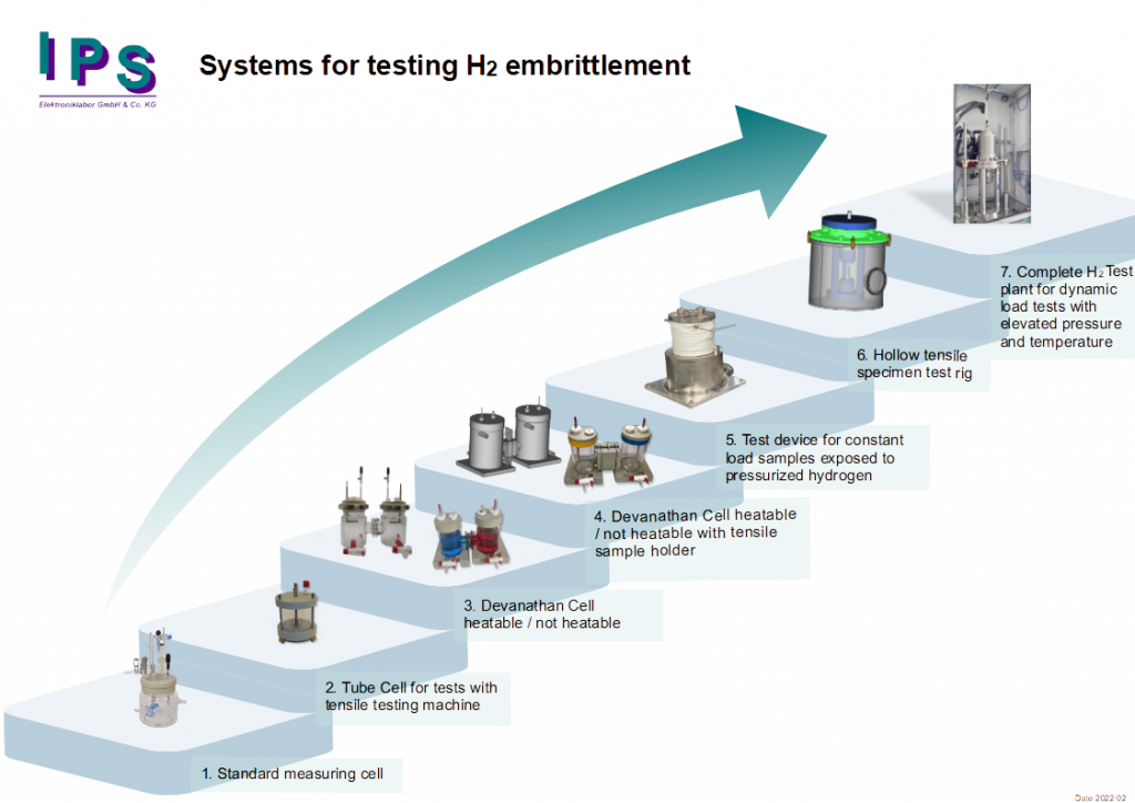
1. Standard measuring cell as an instance for first experiments
Often potentiostats, measuring cells and sometimes even tensile machines are present in the laboratories. A tensile specimen is cathodically polarized in the corrosion measuring cell so that hydrogen is generated. This hydrogen penetrates into the sample (if necessary with the help of thio-urea and temperature). After a defined time, the specimen is removed from the cell, clamped in a tensile testing machine and mechanically loaded until the specimen breaks. A “normal” sample shows the typical necking at the fracture point, a sample damaged with H2 shows a brittle fracture.
Equipment requirement:
- Potentiostat / Galvanostat
- Measuring cell
- Tensile testing machine
- Optional: thermostat
2. Tube Cell for test with a load testing machine
With the use of TubeCell, the above process can be performed in one. The round tensile specimen is simultaneously tensed and electrochemically polarized. This can significantly reduce the experiment time.
Equipment requirements:
- Potentiostat / Galvanostat
- TubeCell as measuring cell
- Load testing machine.
3. Devanathan Cell heatable / not heatable
A Devanathan Cell, often called a double-half cell, allows a sample to be clamped as in a membrane. On the left side, usually called the charging side, hydrogen is generated electrochemically (possibly also purely chemically by pickling), which rises but also diffuses through the steel. On the right side, usually called the measuring side, the hydrogen-induced current is measured electrochemically. Such a sample, usually a flat sample, can also be drawn to the point of fracture after polarization in the load testing machine.
Equipment requirements:
- 1 or 2 Potentiostat(s) / Galvanostat(s)
- Devanathan Cell
- Optional: load testing machine, thermostat
4. Devanathan Cell heatable / not heatable with tensile sample holder
Devices setup as under 3, but here the tensile specimen is inserted directly into a tensile specimen holder developed by us for Devanathan cells. The sample is exposed electrochemically to hydrogen permeation and mechanically to tensile stress.
Equipment requirements:
- 1 or 2 Potentiostat(s) / Galvanostat(s)
- Devanathan cell
- Tensile specimen holder for Devanathan cell
- Optional: tensile testing machine, thermostat.
5. Test device for constant load samples exposed to pressurized hydrogen
This compact unit contains three small autoclaves, a high pressure pump (1000bar) and a heater (200 °C). The samples are mechanically preloaded with a small “constant load” tension device and placed completely into the autoclaves (3 samples at a time). Then the autoclaves are brought to nominal pressure and heated. By this device samples can be loaded from the outside with pressurized hydrogen and with temperature. After a defined measuring time, the experiment is terminated and the samples are removed from the autoclaves. If they are not broken, this can be done by clamping them in a load system. The same can be done with 4-point bend specimens.
Equipment requirements:
- Test stand with autoclaves
- Heating and control system
6. Hollow tensile specimen test rig
This equipment consists of a tensile testing machine (tensile and compression), a booster system (1000bar) with valves and control, a vacuum chamber with valves and control and, if necessary, a residual gas analysis. The hollow-drilled sample is first evacuated and then pressurized with 1000bar hydrogen. The permeation flow path here is from the inside to the outside. The sample is surrounded by a vacuum chamber, the ambient air is evacuated and the user can, for example, perform a residual gas analysis in the vacuum circuit to detect the diffused hydrogen. The vacuum chamber also has a safeguarding effect. If the sample breaks, the hydrogen contained in the sample and pipeline escapes into the chamber and is exhausted. No hydrogen will be released into the laboratory. Furthermore, there is a heating device for the sample, which causes additional stress to the sample. In addition to the duration of the experiment and the residual gas analysis, the fracture pattern can also provide further information about the progress of the experiment. Since such a system is already at significantly higher prices, it is also possible here, for instance, to initially supply only the high-pressure part. This enables such projects to be split up and, if necessary, smaller budgets to be used up.
Equipment requirements:
- Load testing machine
- Booster system (1000bar)
- Vacuum equipment
- Safety-related control system
- Optional: residual gas analysis
7. Complete H2 test plant for dynamic load test with elevated pressure and temperature
This test plant offers the possibility of mechanically loading tensile specimens in an autoclave under pressure and temperature. This ensures a wide variety of experiments. Due to the large quantities of hydrogen 1000 liters and more that can escape here even under moderate test conditions, a comprehensive safety concept with appropriate control is necessary here. Such a plant has to be approved by the local TÜV before commissioning.
Equipment requirements:
- Servo-hydraulic load testing machine
- Autoclave
- Protective chamber with venting via roof
- Distribution cabinet for instruments and valves for gas control and gas measurement
- Cyrostat
- Safety-related control system
On-site infrastructure
The clarification of the on-site infrastructure plays a decisive role before the procurement of a test facility. In addition to the structural planning of the buildings or laboratories in which such systems are to be set up, the operator must be aware that the corresponding test and purge gases must be kept available.
Due to the ignitability of certain gases such as H2, CH4, etc., it is necessary to store these gases, which can usually be obtained in cylinders or cylinder bundles, outside buildings in well-ventilated and lockable areas if possible. Ventilation there alone provides a high degree of safety. In addition to avoiding direct sunlight, care should also be taken to ensure that lightning and surge protection is effectively installed. Furthermore, it makes sense to equip such a location at least simply (if not redundantly) with appropriate gas sensors in order to at least be able to detect leaks. Appropriate shut-off devices must also be installed in order to lead the gases via a central line to the desired laboratories. All installations must be carried out professionally by approved companies and, if necessary, confirmed by an inspection from a certified institute (TÜV, Dekra).
If a higher degree of automation is desired, controllable valves can also be installed at the tapping point. Pressure gauges, which provide indirect information about the filling level, are used to complete the functionality. Valves and sensors should then be routed via a central PLC (Programmable Logic Controller) and the information made available to the respective systems. For example, there is the simple function of monitoring a minimum filling quantity. If the level falls below this, the test systems receive a corresponding signal or a lockout, so that no further experiments can be started that would probably not be completed with this filling level.
Furthermore, it must be considered whether the planned test gases are lighter (H2) or heavier (H2S) than air, so that appropriate safety precautions can be taken.
If experiments are planned with a pressure of up to 50bar, this can be carried out, for example, with H2 with the inherent pressure of a cylinder and one can consume about 75% of the quantity provided. If experiments with lower pressure than 50bar are also carried out, the degree of utilization can still be increased.
However, if higher pressures are planned, the use of a pressure boosting system is recommended. Especially in this scenario, careful planning also has a financial impact. If several test systems were to be used, each equipped with its own pressure boosting system, this would not only increase the costs noticeably, but would also require significantly more space for the installation of these systems. The correspondingly required safety equipment would also significantly increase the investment sum. There are only two reasons for installing multiple booster sets: the required quantity and spontaneous availability. If these reasons can be excluded by smart planning of the experiments, then all test stands are connected by installing one booster system and a ring line.
Each outlet is designed to be shut off with a manual valve, so that each test stand is supplied with its own control (diaphragm valves) at this tap. The compressors feeding the piping system operate independently under pressure control. As soon as the pressure in the pipeline drops due to withdrawal, the compressor starts and increases the pressure up to the preset final value (e.g. 1000bar). This is technically quite easy to handle by using appropriately specified pipes. Only if a larger volume is required and the supply of a corresponding volume at high pressure is necessary, the high-pressure line would have to be extended by an appropriately specified pressure vessel.
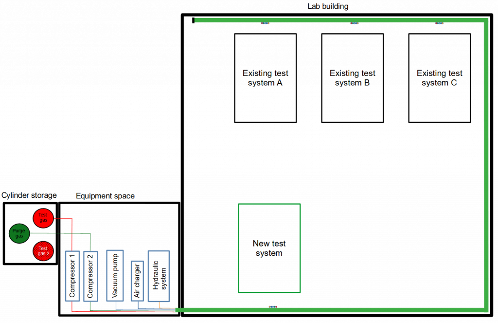
Sketch of a lab building with several test stations, an extra equipment space and a cylinder storage. Every single station is supplied with different gases, vacuum, compressed air and hydraulic system via this ring line (light green color).
Related guidelines
Realizing such a project, one has to apply the following directives:
- Pressure Vessel Directive
- Machinery Directive
- ATEX Directive
- Low Voltage Directive.